
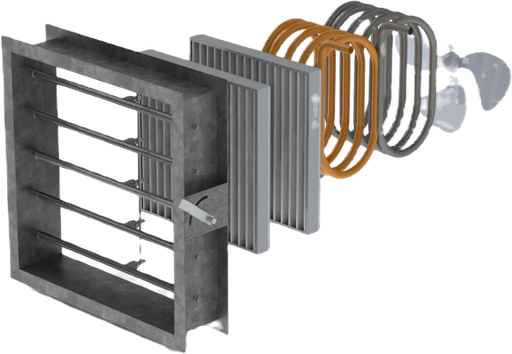
Transfer Pass-thru Duct
INSTRUCTIONS:
Review the methodology to ensure it aligns with your project's requirements.
-
Enter the supply air volume for the room.
-
Select the transfer duct type: Pass-Through, Transfer-Flex, or Transfer-Hard.
-
Select the supply duct material: Flex (Flexible) or Hard to estimate the supply duct size.
-
Click the Calculate button (may not be necessary).
-
View the Results Table for the minimum grille size and duct dimensions required to meet the Florida Building Code (FBC) §601.6, ACCA Manual D, and good-engineering practice.
Sizes the passive return path out of a room against the supply air that room is given, to the two exceptions of 2023 Florida Building Code, Mechanical, Section 601.6. A transfer duct has to be 1.5 times the cross-section of the supply duct entering the room; a transfer grille has to give 50 square inches of free area per 100 CFM of supply air. Both are reported. Either way the door needs an unrestricted 1 inch undercut, which is a requirement of the same section and not a result this page can compute.
The supply duct is not asked for, it is estimated. The workbook sizes it by the equal-friction method at 0.1 in. wg per 100 ft, which is ordinary residential practice, and the transfer duct is 1.5 times the area that gives. If the supply duct is already drawn, its real cross-section is the better number to multiply by 1.5.
The supply duct material selects the roughness that estimate is sized at, but only through the transfer duct type. Flex gives flex, 0.00775 ft. Rigid gives duct board, 0.0019 ft, for a Pass Through or a Transfer - Hard, and flex again for a Transfer - Flex; the workbook's Metal roughness, 0.0003 ft, is never reached. The choice moves the estimated diameter by roughly a fifth of an inch at 50 CFM and by an inch at 2332, so it is worth knowing which one is being reported. This is kept as published.
The sample grille schedule is twenty-six grilles from a residential catalogue, each entered as a neck size and a free area, and every field is editable so the schedule can be replaced with the one actually being specified. A grille's row reports the transfer duct it needs and the largest supply air volume that grille's free area can return, again at 50 square inches per 100 CFM. The published version hides the rows that do not qualify; this one lists them all, so compare each row's maximum supply air against the volume entered.
For a Pass Through or a Transfer - Hard the transfer duct is the grille neck itself, so the size reported on each row is that grille's own neck. For a Transfer - Flex it is round, and every row reports the same diameter: the equivalent diameter of the one minimum area at the top of the page.
Transfer - Hard carries a trailing space in the published dropdown. It is kept as published so the entry still matches.
Corrected 2026-09: clearing the supply air volume, or typing it in scientific notation, used to report 'Inputs over 2332 CFM are invalid!'. The previous version read the box with a converter that hands anything it cannot parse straight through as text, and text outranks every number in the comparison that follows, so an empty box and 1e3 both failed a ceiling that 1000 passes. Nothing else on the page moved, and a volume that really is above 2332 CFM is still flagged.
Return Air Transfer Duct and Pass-Through Grille Sizing Methodology
Purpose
This methodology establishes the design criteria for sizing return air transfer ducts and pass-through grilles in accordance with the 2023 Florida Building Code (FBC) Section 601.6 and 2024 International Mechanical Code (IMC) Section 401.5 to achieve proper return air balance in residential HVAC systems. The procedure applies to typical single-family and multifamily residential spaces where transfer ducts or grilles are used to maintain balanced return airflow between rooms.
Code Requirements
2023 FBC, Section 601.6 - Balanced Return Air
Exception 1:
Transfer ducts may be employed to achieve air balance by increasing the return transfer 1-1/2 times the cross-sectional area (square inches) of the supply duct entering the room or space it is serving, and the door having at least an unrestricted 1-inch undercut to achieve proper return air balance.
Exception 2:
Transfer grilles shall use 50 square inches (of grille area) to 100 CFM (of supply air) for sizing through-the-wall transfer grilles and using an unrestricted 1-inch undercutting of doors to achieve proper return air balance.
2024 IMC, Section 401.5 - Return Air Openings
Return and transfer openings shall be sized in accordance with the appliance or equipment manufacturer's installation instructions, ACCA Manual D, or the design of the registered design professional.
Design Methodology
Step 1: Determine Supply Duct Cross-Sectional Area
The supply duct area entering the room is estimated using the Equal Friction Method with a design friction rate of 0.1 in. w.g. per 100 ft of duct length, which is standard practice for residential duct design.
Equation 1: Supply duct area estimation
A_supply ≈ Q / V
Where:
-
A_supply = Supply duct cross-sectional area (ft²)
-
Q = Supply airflow (CFM)
-
V = Design velocity at 0.1 in w.g. friction rate (typically 700-900 FPM for residential)
For residential applications, ACCA Manual D provides friction rate charts that correlate CFM to duct size at 0.1 in w.g./100 ft.
Design Note: Transfer duct and grille sizing is not a critical design dimension that significantly impacts system performance. The 1.5× multiplier is a minimum code requirement per FBC 601.6, and the grille area requirements (50 sq in per 100 CFM) ensure adequate return air balance. The assumption of 0.1 in w.g./100 ft friction rate for estimating supply duct size is acceptable for typical residential duct runs and provides consistent results across different projects. Minor variations in the estimated supply duct area do not significantly affect compliance, as the code-required multipliers ensure adequate transfer capacity. If actual supply duct dimensions are known from the design drawings, those values may be used directly.
Step 2: Calculate Minimum Transfer Duct Area
Per FBC 601.6 Exception 1, the transfer duct must be 1.5 times the supply duct area:
Equation 2: Minimum transfer duct area
A_transfer(min) = 1.5 × A_supply
The supply duct cross-sectional area is estimated using 0.10 in w.g. friction rate and the duct material selected by the user.
The 1.5× multiplier is a minimum requirement to offset frictional and velocity losses in the return air path and provide sufficient cross-sectional area for pressure equalization.
Step 3: Calculate Minimum Grille Free Area
Per FBC 601.6 Exception 2, grilles must provide 50 sq in per 100 CFM of supply air:
Equation 3: Minimum grille free area
A_grille(min) = Q × (50 sq in / 100 CFM) = 0.5Q sq in
Converting to square feet:
A_grille(min) = 0.5Q / 144 ft²
The minimum grille free area (Ak) represents the total unobstructed area of the grille face and should meet or exceed A_grille(min).
Step 4: Determine Transfer Duct Dimensions
For pass-through installations with height restrictions (framing limitations), calculate the required length:
Equation 4: Required duct length
L_duct = A_transfer(min) × 144 / H_duct
Where:
-
L_duct = Required duct length (inches)
-
H_duct = Available duct height (inches)
-
144 = conversion factor (sq in/ft²)
When height restrictions or framing conditions limit duct geometry, increase duct length to maintain equivalent area.
Step 5: Verify grille selection
Select a grille whose Ak (free area) ≥ A_grille(min).
From sample data, an 8×6 grille (Ak = 0.22 ft²) exceeds the minimum requirement of 0.1736 ft².
Design Example
Given:
-
Supply airflow to bedroom: Q = 50 CFM
-
Available transfer duct height: H_duct = 6 inches
-
Transfer duct type: Pass-through
Solution:
Step 1: Estimate supply duct area Using ACCA Manual D friction rate chart at 0.1 in w.g./100 ft for 50 CFM:
-
Supply duct ≈ 5" round or 4" × 8" rectangular
-
A_supply ≈ 0.12 ft² (estimated)
Step 2: Calculate minimum transfer duct area
A_transfer(min) = 1.5 × 0.12 = 0.18 ft²
Step 3: Calculate minimum grille free area
A_grille(min) = 0.5 × 50 / 144 = 0.1736 ft²
Step 4: Determine duct dimensions
L_duct = 0.18 × 144 / 6 = 4.32 ≈ 5 inches
Result: Minimum transfer duct size = 6" H × 5" L
From sample grille schedule, an 8" × 6" grille (Ak = 0.22 ft²) exceeds the minimum requirement of 0.1736 ft².
Additional Requirements
-
Door Undercut: All doors serving rooms with transfer grilles must have a minimum 1-inch unrestricted undercut for proper return air balance (FBC 601.6).
-
Habitable vs. Non-Habitable Rooms: Per FBC 601.6 Exception 3, habitable rooms only shall be required to meet balanced return air requirements. Bathrooms, closets, storage rooms, and laundry rooms are excluded, except that all supply air into the master suite shall be included.
-
Grille Selection: Use the manufacturer's Ak (free area) values when selecting grilles. Ensure selected grille Ak ≥ A_grille(min).
References
-
Florida Building Code, Mechanical (2023), Section 601.6, "Balanced Return Air"
-
International Mechanical Code (2024), Section 401.5, "Return Air Openings"
-
ACCA Manual D, "Residential Duct Systems," Air Conditioning Contractors of America
-
ACCA Manual J, "Residential Load Calculation," 8th Edition
This methodology is intended for use by licensed mechanical engineers and designers. Always verify compliance with local codes, manufacturer specifications, and project-specific requirements.